The whole Arduino line follower robot can be divided into 3 sections: sensor section, a control section, and driver section.
Sensor section:
This section contains IR diodes, potentiometer, Comparator (Op-Amp) and LED’s. The potentiometer is used for setting reference voltage at comparator’s one terminal and IR sensors are used to sense the line and provide a change in voltage at the comparator’s second terminal. Then the comparator compares both voltages and generates a digital signal at the output. Here in this line follower circuit, we have used two comparators for two sensors. LM 358 is used as a comparator. LM358 has inbuilt two low noise Op-amps.
Control Section:
Arduino Pro Mini is used for controlling the whole the process of the line follower robot. The outputs of comparators are connected to digital pin numbers 2 and 3 of Arduino. Arduino read these signals and send commands to driver circuit to driveline follower.
Driver section:
The driver section consists of motor driver and two DC motors. The motor driver is used for driving motors because Arduino does not supply enough voltage and current to the motor. So we add a motor driver circuit to get enough voltage and current for the motor. Arduino sends commands to this motor driver and then it drives motors.
Working of Line Follower Robot using Arduino
Building a Line follower robot using Arduino is interesting. The line follower robot senses a black line by using a sensor and then sends the signal to Arduino. Then Arduino drives the motor according to sensors' output.
Here in this project, we are using two IR sensor modules namely the left sensor and the right sensor. When both left and right sensor senses white then the robot moves forward.
If the left sensor comes on a black line then the robot turn the left side.
If the right sensor sense black line then robot turn right side until both sensors comes at the white surface. When the white surface comes robot starts moving on forward again.
If both sensors come on the black line, the robot stops.
Circuit Diagram
The complete circuit diagram for arduino line follower robot is shown in the above image. As you can see the output of comparators is directly connected to Arduino digital pin number 2 and 3. And motor driver’s input pin 2, 7, 10 and 15 is connected to Arduino's digital pin number 4, 5, 6 and 7 respectively. And one motor is connected at the output pin of motor drivers 3 and 6 and another motor is connected at pin 11 and 14.
Working of Line Follower Robot
The concept of the line follower robot is related to light. Here, we use the behavior of light on the black-and-white surface. The white color reflects all the light that falls on it, whereas the black color absorbs the light.
In this line-follower robot, we use IR transmitters and receivers (photodiodes). They are used to send and receive the lights. When IR rays fall on a white surface, they are reflected toward the IR receiver, generating some voltage changes.
Black surfaces absorb infrared radiation and do not reflect any of the rays that fall on them; therefore, no photons reach the infrared receiver.
In this project, when the IR sensor senses a white surface, an Arduino gets 1 (high) as input, and when it senses a black line, an Arduino gets 0 (low) as input. Based on these inputs, an Arduino Uno provides the proper output to control the bot.
Also, it requires therobot chassisto mount all the above components on it. A robot chassis is an optional component; you can also make the robot chassis using cardboard.
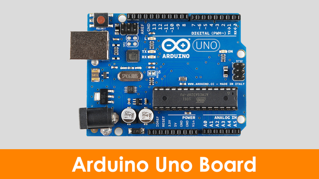
Arduino Uno
Arduino Uno is an 8-bit ATmega328P microcontroller. To support the microcontroller, it uses components such as a crystal oscillator, serial communication, voltage regulator, etc. It has 14 digital I/O pins( 6 pins can be used as PWM pins). It has six separate analog input pins, a USB connection, a power barrel jack, an ICSP header, and a reset button.
This board is programmable with the Arduino IDE (Integrated Development Environment) platform via a type B USB cable. This board can be powered via a USB cable or an external voltage ranging from 7 to 20 volts. To know more about an Arduino Uno, refer to the article, what is Arduino Uno?
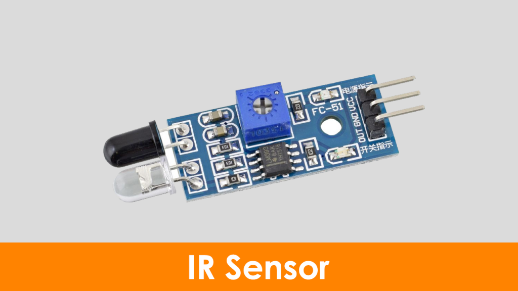
Infrared Sensor
An infrared sensor emits light to detect certain surroundings. In the infrared spectrum, all the objects radiate some form of thermal radiation that is invisible to our eyes, but an IR sensor can detect these radiations.
Here, the IR LED is an emitter, and the IR photodiode is a detector. An IR LED emits the IR light, and the photodiode is sensitive to this IR light. When IR light falls on the photodiode, the output voltages and the resistances will change in proportion to the magnitude of the received IR light.
The infrared detection system uses five essential elements: an infrared source, a transmission medium, an optical component, infrared detectors, and signal processing. Infrared transmission can be done through the vacuum, atmosphere, and optical fibers. To know more about the IR sensor, refer to the article on the working principle of IR sensors.
L298N Motor Driver
L298N is one of the easiest and best ways to control DC motors. It is the two-channel motor driver that can control the speed and spinning direction of DC motors.
This L298N motor driver is a high-power motor driver module. It is used for driving DC and stepper motors. This motor driver consists of an L298N motor driver IC and a 78M05 5V voltage regulator, resistors, capacitor, power LED, and 5V jumper in an integrated circuit.
When the jumper is placed, it enables the 78M05 voltage regulator. When the power supply is less than or equal to 12 volts, the voltage regulator will power the internal circuitry. When the power supply is more than 12 volts, then the jumper should not be placed and should give a separate 5 volts to power the internal circuitry.
Here, the ENA and ENB pins are speed control pins for Motor A and Motor B. IN1 and IN2 and IN3 and IN4 are direction control pins for Motor A and Motor B.
BO Motors
A BO motor is known as a battery-operated motor. These motors are commonly used in hobby-grade projects where the user requires a small DC motor as a simple actuator.
BO series linear motors provide good torque and rpm at lower operating voltages. The BO motors are available in single-shaft, dual-shaft, and DC plastic gear BO. These motors consume a low current. In this project, we have used four single-shaft BO motors.
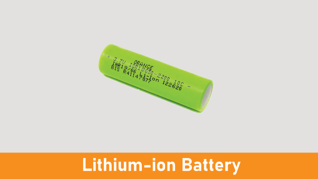
Lithium-ion Battery
A lithium-ion battery is a rechargeable battery. It is commonly used in portable devices such as mobiles, laptops, electronics, and electric vehicles. Also, they are growing in popularity for military and aerospaceapplications.
A lithium-ion battery provides 3.7V in storage mode and 4.2V in full charge mode. In this project, we have connected two lithium-ion batteries in series so that the total battery voltage will be 8.4V at full charge. To know more about lithium-ion batteries, refer to the article on the working of Lithium-ion batteries.
Connection Diagram of Line Follower Robot
Here, we have used four BO motors. Motors 1 and 2 are connected to the first channel of L298N, whereas motors 3 and 4 are connected to the second channel of the motor driver.
IN1, IN2, IN3, and IN4 pins are connected to pins 9, 6, 5, and 3 of the Arduino Uno. Here, we have used the jumper between +5V and the enable pins (EN1 and EN2). You can remove it and make the external connection, as shown in the below image.
Essentially another tutorial involving controlling DC motors. In this post I’m going to first alter a robot arm I had built previously from a beginners kit so that it can be controlled from Arduino. Then I’m going to write a series of posts on different ways to control the robot arm using Processing and other things. You should be able to use all of what I write for work with other toys and motors. To start with have a look at the robot arm, it’s an ‘Edge Robotic Arm Kit‘: The kit is a basic construction one and costs about £30 which you can find in most gadget shops and web stores. You assemble a gear box for each motor/ joint in the arm, doesn’t take long to build (about an hour) and is controlled by a set of switches on a control box. The only thing to note here is we’re dealing with motors, not servos or stepper motors just bog standard DC motors. This means calculating positions isn’t going to be straightforward later on. The kit has 5 motors and 4 ‘D’ series batteries to power them and can lift about 100 grammes. So this version has a controller attached that lets you move each motor by pressing a switch, the electrics are pretty basic and don’t allow much control or further input. I have seen other versions that allow you to plug it in to a computer via USB but you pretty much have the same controls. In order for us to build our own controls/ interfaces and software we need to modify the arm to allow us to interface our microcontroller – in this case an Arduino board. The best way I think do this, since we want to control a motor going backwards and forward, is to use H-bridge chips – the L293D and SN754410 and wire each motor into a chip and then alter the power circuit to run these chips. Arduino can then digitally control the H-bridge chip to turn the motor on/off and change its direction. You can see some other work I’ve done with motor DC motor control and I’ll be covering the same info throughout these posts.
Arduino Robot Arm Parts
3 H-bridge chips – I heavily recommend using the sn754410 chip but you can probably get away with the L293 series. Each chip can control 2 motors – 5 motors = 3 chips. Arduino Deumilanova w/ ATMEGA328 Breadboard/ Prototyping board Jumper/ Connector wires Wire cutters/ strippers
Hacking the Robot Arm
I hope you’re not too precious about wanting to use the control unit again, thats the first thing to go! I did look at working with this but it doesn’t give the level of control that I want. Also I’ll be cutting and stripping the wires and removing the control circuit from the arm. The only permanent damage is done to the wires – basically cutting the plugs off of the wires, so you could always get new plugs if you wanted to revert it, although once I’ve shown you what can be done I don’t think you’ll mind. Step 1 First we need to create our breadboard layout so we can plug in all the wires, we’re going to be using alot of pins on the Arduino, in fact I think I use pretty much all of them. You could reduce this using shift registers but for now its not an issue, although please follow the wiring diagrams as this layout gives the least hassle. Some pins e.g. digital pin 13 will make the motors move when the board is powering up so we want to avoid this. First of all we need to put our H-Bridge chips on the breadboard. Make sure to put them in the center like illustrated. This means the 2 sides of the chip are isolated – it will not work otherwise! Next using the above image and the following wiring diagram for the chip connect the ground and power for each chip leaving space for the motors and Arduino pins. Note that the red wires are connecting the rails together so the power will flow around the whole board! These chips will be using the battery power that runs the motors in the arm – the power will be plugged into the board, the Arduino pins are there to switch the chips on/ off etc… I’ve also got a table of outputs I’ve done for each pin on the H-Bridge chip, it’s the same for either the L293 series or SN754410, pin configuration diagram below. The numbers 1-16 also correspond to the numbers on the images of the circuit.
A while back, I completed a MOOC (massive open online course) about robotics, which got me immersed in the amazing world of robot arms. Being involved for some time with tinkering and electronics, I decided I was going to build my own robot arm and try to implement everything I had learned in that course in the “real world.”
I decided to create an Arduino controlled robot arm that I could use as a platform to test all the theory that had been covered, and experiment with new ideas. I also wanted to be able to interface to the arm in as many ways as I could imagine with other devices (such as my laptop, smartphone, etc.). This would allow for future development, like adding robotic vision by means of a webcam.
Let’s start first with some theory and basic concepts about robot arms.
WHAT DOES “DEGREE OF FREEDOM” (DOF) MEAN EXACTLY?
Surely, one of the first questions for those new to robotics or mechanics is: What does “Degree of Freedom” mean? The DOF of a mechanical system is a specific mode in which said system can move; that is, a rotational or a translational movement.
In the case of robot arms, rotational and translational movements are produced by revolute and prismatic joints, respectively. Most types of robot arms have only revolute joints, materialized with servos. To find out how many degrees of freedom a robot arm has, it is enough to just count the amount of servos since each servo provides one DOF (of rotational movement). So: Number of servos = Number of DOF. Easy!
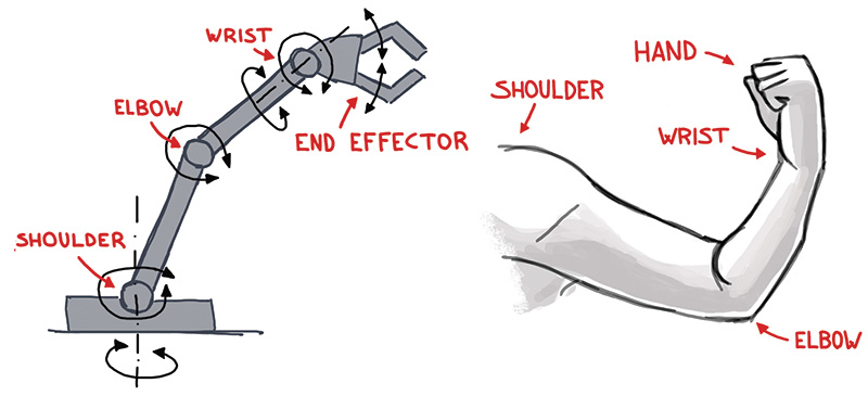
PARTS OF A SIX DOF ROBOT ARM
Why exactly six DOF? Because six DOF is the minimum that an arm needs to be able to reach to any point within a specific volume of space from every possible angle with its end effector (claw, manipulator, hand, etc.). Many industrial and hobbyist robot arms have six DOF.
A robot arm can be compared with a human arm, which has at least six DOF. As observed in Figure 1, the robot arm also has a shoulder, elbow, wrist, and “hand” (end effector). Note that the shoulder and the wrist of the robot arm have two DOF each, as there are two perpendicular servos whose axes intersect in the joint.
FIGURE 1. Comparison of robot arm and human arm.
An arm with less than six DOF is classified as an “under-actuated” arm, whereas an arm with more than six DOF is a “redundant arm.”
HOW TO CALCULATE MOTION: FORWARD AND INVERSE KINEMATICS
Let’s see how a robot arm can be controlled. There are two approaches to this:
Forward kinematics: The end effector space coordinates and orientation (from now on “pose”) are calculated considering a given set of joint angles.
Inverse kinematics: The joint angles are calculated considering a given end effector pose.
It is clear that in most cases, we will need to bring the end effector to a specific pose and therefore calculate the necessary joint angles, which means that we will have to deal with inverse kinematics! Inverse kinematics is rather complicated compared with forward kinematics, and there are different approaches to solve this problem:
Algebraic solution: Very complicated equations in matrix form are needed.
Numerical solution: Provides an initial guess of the joint angles and performs iterations to minimize the error.
Geometric solution: Uses trigonometry based on the robot arm geometry.
Although the geometric solution may get very complicated for complex arms, a simplified model was my choice, as it was the easiest method to implement in the Arduino code. (More details on this will follow in the second article.)
HOW MY ROBOT ARM WORKS
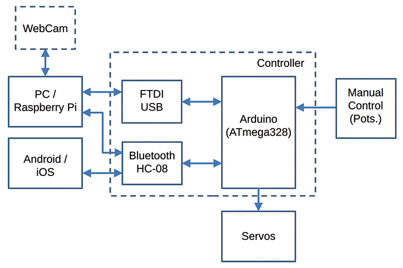
The possibilities of controlling the robot arm from a PC/Raspberry Pi through the serial port (USB) are almost infinite: Matlab or Python script, Processing, Robot Operating System (ROS), Arduino IDE (integrated development environment; serial monitor), etc. The controller also interfaces with an Android/iOS device (tablet, smartphone) through Bluetooth, and can be controlled manually using a “control box” with rotating knobs as well.
An important upgrade that I plan for the future (as previously mentioned) is the addition of robotic vision with a webcam mounted on the end effector and connected to a PC/Raspberry Pi. This way, the robot could recognize different types of objects (by color and/or size) and grab them.
CONSTRUCTION OF THE ROBOT ARM
The robot arm is divided into three main elements:
Robot arm body
Hardware (electronic controller)
Software
In the following sections, I will go through each of these parts.
FIGURE 2. Hardware block diagram.
CONSTRUCTION OF THE ROBOT ARM BODY
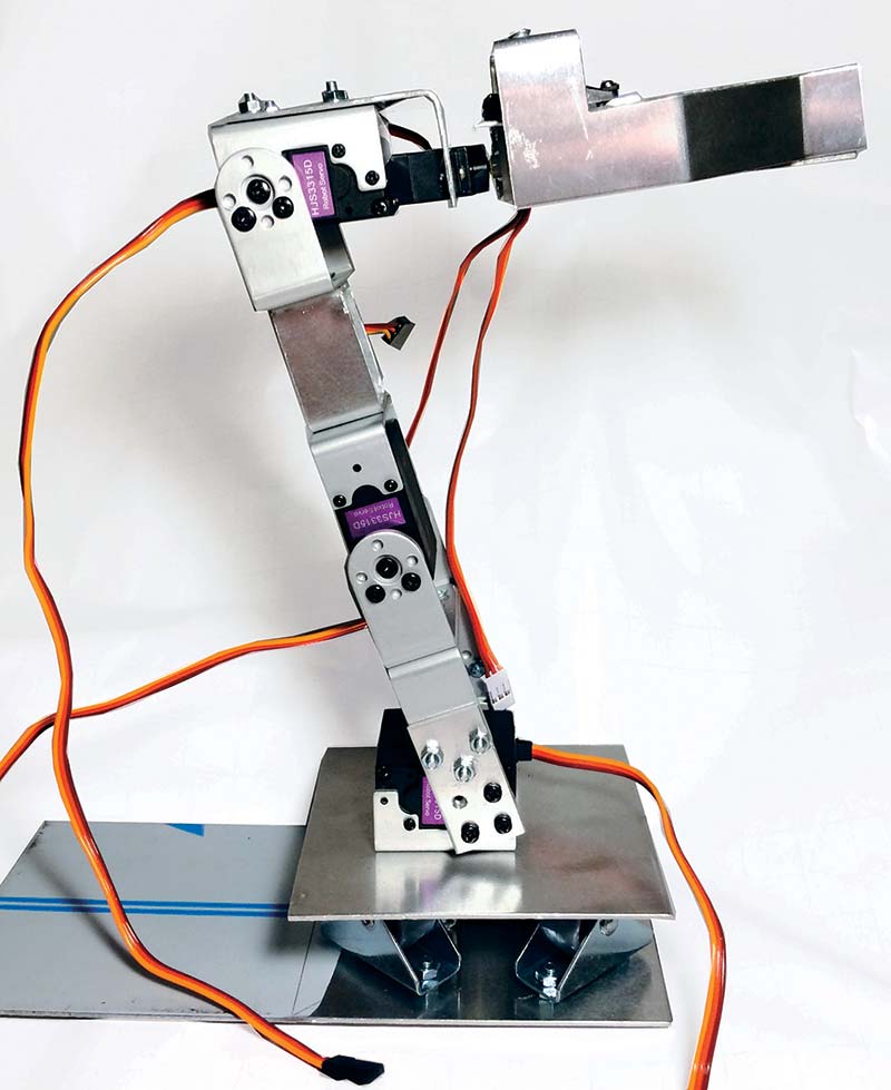
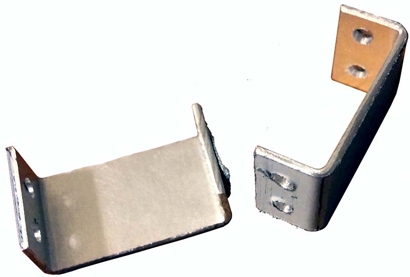
To build the robot arm body (see Figure 3), I purchased some servos on eBay that already included aluminium brackets so that it would be easier to connect the servos to each other, as well as to other elements of the robot arm (see Figure 4 for the aluminium brackets I made).
FIGURE 3. Robot arm body.
These servos rotate up to 180 degrees and their maximum torque is 15 kg, which is more than enough.
FIGURE 4. Aluminium brackets.
The two main challenges that I faced while building the arm body were the design of the base and the end effector.
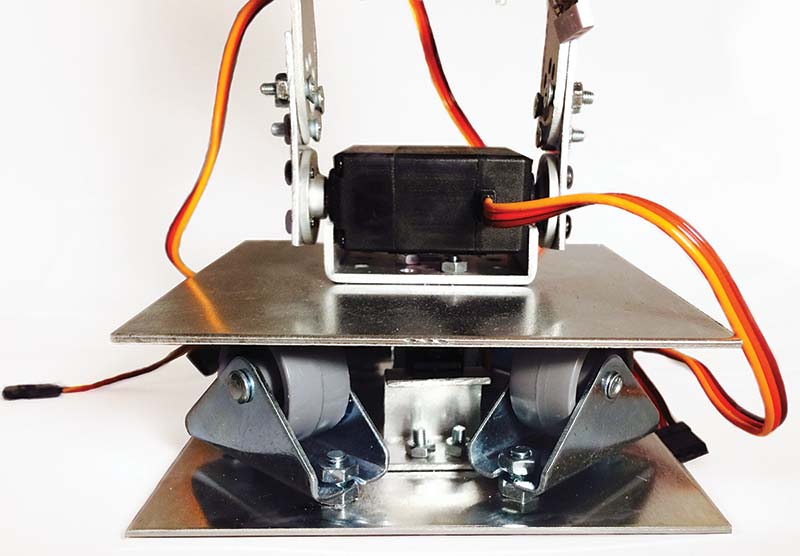
In order for the base to be able to rotate around the vertical axis and be stable enough to stand the whole weight of the arm, I used four small wheels that I found in a DIY store (yes, the kind used for wardrobe doors!). Below the horizontal plate, there’s a micro servo fixed with brackets to the main base (Figures 5 and 6).
FIGURE 5. Robot arm base.
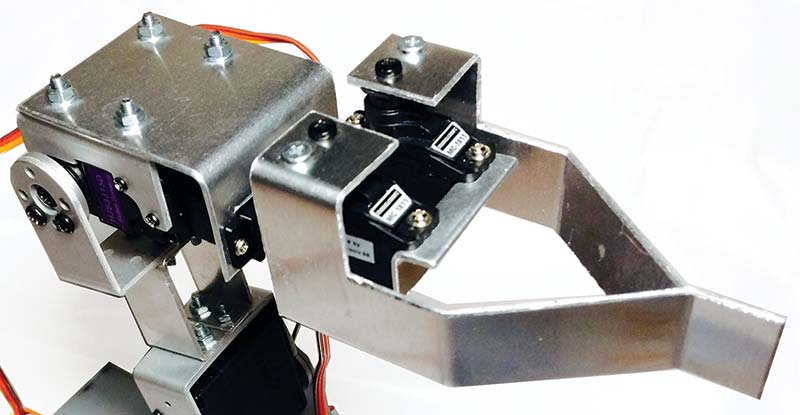
FIGURE 6. Robot arm end effector.
This servo is not very strong, but for now it has done the job and its height is minimal, so the rotating base is kept as low as possible (for the overall center of gravity to be kept in a low position). For the base and end effector, I used servos that can also rotate up to 180 degrees. Otherwise, the robot arm movements would be very limited.
The end effector is rotated by another micro servo. As I couldn’t find a simple way of adding a gear mechanism to control the two “fingers” of the end effector with a single servo, I decided to use two micro servos for controlling the two fingers.
DESIGN AND ASSEMBLY OF THE ELECTRONIC CONTROLLER
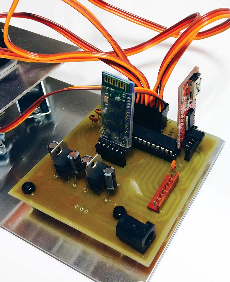
The controller consists of a homemade printed circuit board (PCB) and a control box that is connected to the PCB through a JST 2.0 PH eight-pin connector. The controller “brain” is a stand-alone Arduino chip (ATmega328) that processes all the analog inputs (from PC/Raspberry Pi/Android/iOS/control box) and provides the seven servos with the appropriate output signals (Figure 7).
FIGURE 7. Controller PCB.
The power supply is provided in two independent channels of 5V and 6V for the Arduino chip (and other control elements of the PCB) and the servos, respectively.
This is a very important fact to consider when we include servos or motors in our projects, as they usually present a very high current consumption. If they were directly powered by the same channel as the Arduino (ATmega328) chip, it could basically burn out when the servos get hungry!
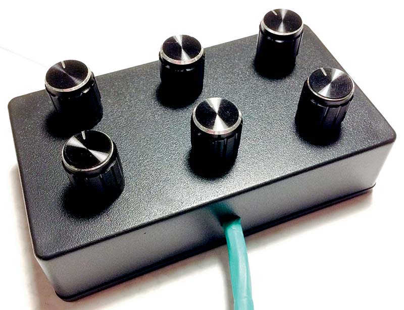
The control box has six rotating knobs which are used to manually control every joint of the robot arm (base, shoulder, elbow, two wrist axes, and end effector); refer to Figure 8.
FIGURE 8. Robot arm control box.
The potentiometers attached to the rotating knobs produce a voltage range that is used as analog input by the Arduino chip. Depending on this input, the Arduino will command the appropriate output signals to the digital pins where the servos are connected.
THE CONTROLLER BOARD
You can see the list of electronic components needed to build the controller board in Parts List.
CONTROLLER BOARD PARTS LIST
DC barrel jack adapter
SPDT slide switch
4x 10 µF capacitors
5V Voltage regulator (LM7805)
6V Voltage regulator (LM7806)
Micro JST 2.0 PH eight-pin male connector plug
2x Female pin header (1x6)
3x Male pin header (1x6)
28-pin DIL IC socket
Atmel ATmega328 chip (DIP28). If it does not have the Arduino bootloader installed, you will need to install it.
16 MHz Crystal
2x 22 pF Capacitor
0.1 µF Capacitor
To design the PCB layout, I used my old beloved friend, KiCad. (KiCad is an open source EDA software for Windows, OSX, and Linux.) I started to use it almost 10 years ago in my first graduate job, and after trying other PCB software, I have always come back to KiCad. Although sometimes a bit tricky to use, it’s open source, the online community for solving issues is pretty big, and it’s always under continuous improvement. Plus, plenty of libraries from Eagle (such as those from SparkFun) are regularly converted into KiCad format.
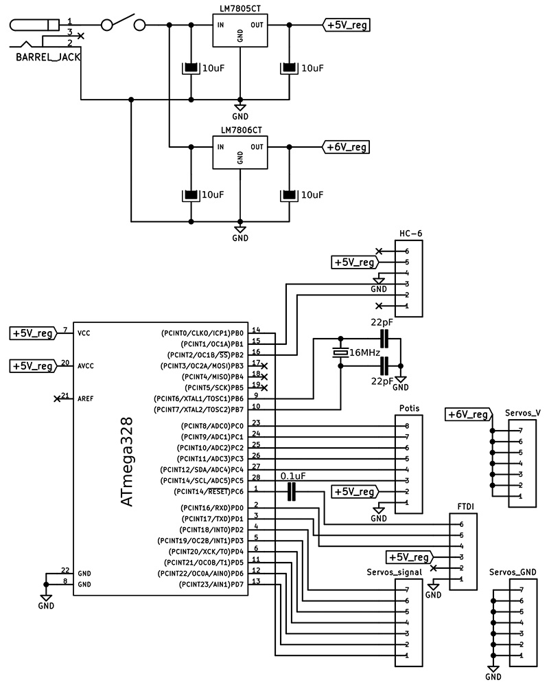
The first step to define the PCB layout is to draw the schematics in Eeschema — KiCad’s schematic editor (Figure 9).
FIGURE 9. Controller board schematics in KiCad.
Then, a “netlist” has to be generated, which is a file that will be required by PcbNew (KiCad’s PCB editor module) to import the needed PCB components properly connected. For newbies, all this may produce more than one headache, but don’t panic! Once you’ve got a bit of practice, it becomes a rather smooth task.
The upper part of Figure 9 shows the voltage regulators, which convert the input voltage (up to 12V according to the datasheet) into two voltage levels in two independent channels: 5V for the Arduino chip (and other control elements), and 6V for the servos. The lower part shows the Arduino chip with the interfaces (pin header connectors) to the following elements:
Control box (“Potis”): Micro JST 2.0 PH eight-pin male connector plug
Servos GND channel (“Servos_GND”): Male pin header (1x6)
Servos 6V channel (“Servos_V”): Male pin header (1x6)
Servos signal channel (“Servos_signal”): Male pin header (1x6)
FTDI232 USB to serial breakout board (“FTDI”): Female pin header (1x6)
HC-06 Bluetooth board (“HC-6”): Female pin header (1x6)


Comments
Post a Comment