Mica Capacitors,
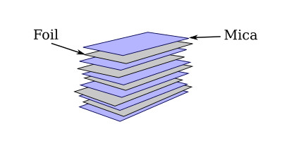
The basic construction of a mica capacitor is shown in the figure below. It consists of a number of flat strips of metal foil separated by similarly shaped strips of mica. The foil strips serve as the capacitor plates, and the mica acts as the dielectric. Alternate plates are connected together. The whole assembly is encased in molded plastic.
An alternate construction is that of the "silvered" mica capacitor. In this construction very thin layers of silver are deposited directly upon one side of the mica, and the plates are stacked together so that alternate layers of silver are separated by alternate layers of mica. The result is the equivalent of the foil construction. This method enables closer manufacturing tolerances to be met, since precision masking techniques permit the area of the deposited plate to be determined with greater accuracy and greater uniformity than in the cut-foil construction. In addition, the thickness of the completed capacitor is less, due to the thinness of the deposited plate.
Mica is an excellent dielectric and can withstand a higher voltage than can a paper dielectric of the same thickness. Common values of mica capacitors range from approximately 10 pF to 100 nF.
Ceramic Capacitors,
A ceramic capacitor is so named because it contains a ceramic dielectric. One type of ceramic capacitor uses a hollow ceramic cylinder as both the form on which to construct the capacitor and as the dielectric material. The plates consist of thin films of metal deposited on the ceramic cylinder.
A second type of ceramic capacitor is manufactured in the shape of a disk. The construction consists of a ceramic disc with metal plates deposited on the opposite faces of the ceramic material. After leads are attached to each side of the capacitor, the capacitor is completely covered with an insulating moisture-proof coating. Ceramic capacitors usually range in value from 1 pF to 100 nF and may be used with voltages as high as 30 kV.

Electrolytic Capacitors,
An electrolytic capacitor is used where a large amount of capacitance is required. As the name implies, an electrolytic capacitor contains an electrolyte. This electrolyte can be in the form of a liquid (wet electrolytic capacitor). The wet electrolytic capacitor is no longer in popular use due to the care needed to prevent spilling of the electrolyte. A dry electrolytic capacitor consists essentially of two metal plates separated by the electrolyte. In many cases the capacitor is housed in a cylindrical aluminum container which acts as the negative terminal of the capacitor. The positive terminal (or terminals if the capacitor is of the multisection type) is a lug (or lugs) on the bottom end of the container. The capacitance value(s) and the voltage rating of the capacitor are generally printed on the side of the aluminum case.

Internally, the electrolytic capacitor is constructed similarly to the paper capacitor. The positive plate consists of aluminum (or tantalum) foil covered with an extremely thin film of oxide. This thin oxide film (which is formed by an electrochemical process) acts as the dielectric of the capacitor. Next to and in contact with the oxide is a strip of paper or gauze which has been impregnated with a paste-like electrolyte. The electrolyte acts as the negative plate of the capacitor. A second strip of aluminum foil is then placed against the electrolyte to provide electrical contact to the negative electrode (the electrolyte). When the three layers are in place they are rolled up into a cylinder.
An electrolytic capacitor has two primary disadvantages compared to a paper or film capacitor in that the electrolytic type is polarized and has a low leakage resistance. This means that should the positive plate be accidentally connected to the negative terminal of the source, the thin oxide film dielectric will dissolve and the capacitor will become a conductor (i.e., it will short). The polarity of the terminals is normally marked on the case of the capacitor. Since an electrolytic capacitor is polarity sensitive, its use is ordinarily restricted to a DC circuit or to a circuit where a small AC voltage is superimposed on a DC voltage. Special electrolytic capacitors are available for certain AC applications, such as a motor starting capacitor. Dry electrolytic capacitors vary in size from about 1 microfarad to several thousand microfarads.
The type of dielectric used and its thickness govern the amount of voltage that can safely be applied to the electrolytic capacitor. If the voltage applied to the capacitor is high enough to cause the atoms of the dielectric material to become ionized, arcing between the plates will occur. In most other types of capacitors, arcing will destroy the capacitor. However, an electrolytic capacitor has the ability to be self-healing. If the arcing is small, the electrolytic will regenerate itself. If the arcing is too large, the capacitor will not self-heal and will become defective.
tantalum capacitors,
 Tantalum capacitors are a subtype of electrolytic capacitors. They are made of tantalum metal which acts as an anode, covered by a layer of oxide which acts as the dielectric, surrounded by a conductive cathode. The use of tantalum allows for a very thin dielectric layer. This results in a higher capacitance value per volume, superior frequency characteristics compared to many other types of capacitors and excellent stability over time. Tantalum capacitors are generally polarized, which means that they may only be connected to a DC supply observing the correct terminal polarity. The downside to using tantalum capacitors is their unfavorable failure mode which may lead to thermal runaway, fires and small explosions, but this can be prevented through the use of external failsafe devices such as current limiters or thermal fuses. Technology advances allow tantalum capacitors to be used in a wide variety of circuits, often found in laptops, automotive industry, cell phones and others, most often in the form of surface mounted devices (SMD). These surface mount tantalum capacitors claim much less space on the printed circuit board and allow for greater packing densities.
General characteristics,
Tantalum capacitors are made with capacitance values ranging from 1nF all the way to 72mF and they are much smaller in size than aluminum electrolytic capacitors of the same capacitance. The voltage rating for tantalum capacitors varies from 2V to more than 500V. They have an equivalent series resistance (ESR) ten times smaller than the ESR of aluminum electrolytic capacitors, which allows for larger currents to pass through the capacitor with less heat generated. Tantalum capacitors are very stable over time and their capacitance doesn’t change with age significantly, especially when compared to aluminum electrolytic capacitors. They are very reliable when handled properly and their shelf life is virtually unlimited.
Polarity
Tantalum electrolytic capacitors are exceptionally polarized devices. While aluminum electrolytic capacitors, which are polarized as well, might survive a briefly applied reverse voltage, tantalum capacitors are very sensitive to reverse polarization. If a reverse polarity voltage is applied, the dielectric oxide breaks down, sometimes forming a short circuit. This short circuit may later cause thermal runaway and destruction of the capacitor.
It should be noted that tantalum capacitors usually have their positive terminal marked, in contrast to aluminum electrolytic capacitors, which have their negative terminal marked on the casing.
Failure mode
Tantalum capacitors have a potentially dangerous failure mode. In case of voltage spikes, the tantalum anode may come in contact with the manganese dioxide cathode, and if the energy of the spike is sufficient it may start a chemical reaction. This chemical reaction produces heat and is self-sustaining and may produce smoke and flame. To prevent this thermal runaway from happening, external failsafe circuitry such as current limiters and thermal fuses should be used in conjunction with tantalum capacitors.
- When a capacitor charges, the current decreases exponentially until it reaches zero. The potential difference and charge increase exponentially over time.
- When a capacitor discharges, the rate of discharge is fastest when the power supply is first removed and then tapers exponentially. The time constant of a discharging capacitor is the time it takes for the charge, current, or potential difference to decrease to 37% of its original value.
Comments
Post a Comment