Arduino Integrated Development Environment (IDE) v1
Learn how the Arduino IDE v1 works, such as compiling & uploading sketches, file management, installing dependencies and much more.
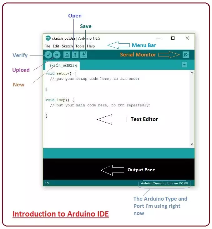
The Arduino Integrated Development Environment - or Arduino Software (IDE) - contains a text editor for writing code, a message area, a text console, a toolbar with buttons for common functions and a series of menus. It connects to the Arduino hardware to upload programs and communicate with them.
Writing Sketches
Programs written using Arduino Software (IDE) are called sketches. These sketches are written in the text editor and are saved with the file extension .ino. The editor has features for cutting/pasting and for searching/replacing text. The message area gives feedback while saving and exporting and also displays errors. The console displays text output by the Arduino Software (IDE), including complete error messages and other information. The bottom righthand corner of the window displays the configured board and serial port. The toolbar buttons allow you to verify and upload programs, create, open, and save sketches, and open the serial monitor.
NB: Versions of the Arduino Software (IDE) prior to 1.0 saved sketches with the extension .pde. It is possible to open these files with version 1.0, you will be prompted to save the sketch with the .ino extension on save.

Verify Checks your code for errors compiling it.

Upload Compiles your code and uploads it to the configured board. See uploading below for details.
Note: If you are using an external programmer with your board, you can hold down the "shift" key on your computer when using this icon. The text will change to "Upload using Programmer"

New Creates a new sketch.

Open Presents a menu of all the sketches in your sketchbook. Clicking one will open it within the current window overwriting its content.
Note: due to a bug in Java, this menu doesn't scroll; if you need to open a sketch late in the list, use the File | Sketchbook menu instead.

Save Saves your sketch.

Serial Monitor Opens the serial monitor.
Additional commands are found within the five menus: File, Edit, Sketch, Tools, Help. The menus are context sensitive, which means only those items relevant to the work currently being carried out are available.
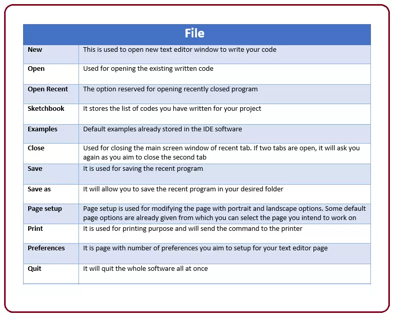
File
New Creates a new instance of the editor, with the bare minimum structure of a sketch already in place.
Open Allows to load a sketch file browsing through the computer drives and folders.
Open Recent Provides a short list of the most recent sketches, ready to be opened.
Sketchbook Shows the current sketches within the sketchbook folder structure; clicking on any name opens the corresponding sketch in a new editor instance.
Examples Any example provided by the Arduino Software (IDE) or library shows up in this menu item. All the examples are structured in a tree that allows easy access by topic or library.
Close Closes the instance of the Arduino Software from which it is clicked.
Save Saves the sketch with the current name. If the file hasn't been named before, a name will be provided in a "Save as.." window.
Save as... Allows to save the current sketch with a different name.
Page Setup It shows the Page Setup window for printing.
Print Sends the current sketch to the printer according to the settings defined in Page Setup.
Preferences Opens the Preferences window where some settings of the IDE may be customized, as the language of the IDE interface.
Quit Closes all IDE windows. The same sketches open when Quit was chosen will be automatically reopened the next time you start the IDE.
Edit
Undo/Redo Goes back of one or more steps you did while editing; when you go back, you may go forward with Redo.
Cut Removes the selected text from the editor and places it into the clipboard.
Copy Duplicates the selected text in the editor and places it into the clipboard.
Copy for Forum Copies the code of your sketch to the clipboard in a form suitable for posting to the forum, complete with syntax coloring.
Copy as HTML Copies the code of your sketch to the clipboard as HTML, suitable for embedding in web pages.
Paste Puts the contents of the clipboard at the cursor position, in the editor.
Select All Selects and highlights the whole content of the editor.
Comment/Uncomment Puts or removes the // comment marker at the beginning of each selected line.
Increase/Decrease Indent Adds or subtracts a space at the beginning of each selected line, moving the text one space on the right or eliminating a space at the beginning.
Find Opens the Find and Replace window where you can specify text to search inside the current sketch according to several options.
Find Next Highlights the next occurrence - if any - of the string specified as the search item in the Find window, relative to the cursor position.
Find Previous Highlights the previous occurrence - if any - of the string specified as the search item in the Find window relative to the cursor position.
Sketch
Verify/Compile Checks your sketch for errors compiling it; it will report memory usage for code and variables in the console area.
Upload Compiles and loads the binary file onto the configured board through the configured Port.
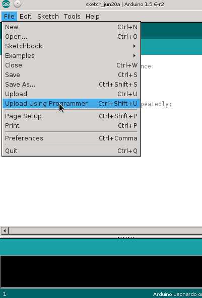
Upload Using Programmer This will overwrite the bootloader on the board; you will need to use Tools > Burn Bootloader to restore it and be able to Upload to USB serial port again. However, it allows you to use the full capacity of the Flash memory for your sketch. Please note that this command will NOT burn the fuses. To do so a Tools -> Burn Bootloader command must be executed.
Export Compiled Binary Saves a .hex file that may be kept as archive or sent to the board using other tools.
Show Sketch Folder Opens the current sketch folder.
Include Library Adds a library to your sketch by inserting #include statements at the start of your code. For more details, see libraries below. Additionally, from this menu item you can access the Library Manager and import new libraries from .zip files.
Add File... Adds a supplemental file to the sketch (it will be copied from its current location). The file is saved to the
subfolder of the sketch, which is intended for assets such as documentation. The contents of thedata
folder are not compiled, so they do not become part of the sketch program.data
Tools
Auto Format This formats your code nicely: i.e. indents it so that opening and closing curly braces line up, and that the statements inside curly braces are indented more.
Archive Sketch Archives a copy of the current sketch in .zip format. The archive is placed in the same directory as the sketch.
Fix Encoding & Reload Fixes possible discrepancies between the editor char map encoding and other operating systems char maps.
Serial Monitor Opens the serial monitor window and initiates the exchange of data with any connected board on the currently selected Port. This usually resets the board, if the board supports Reset over serial port opening.
Board Select the board that you're using. See below for descriptions of the various boards.
Port This menu contains all the serial devices (real or virtual) on your machine. It should automatically refresh every time you open the top-level tools menu.
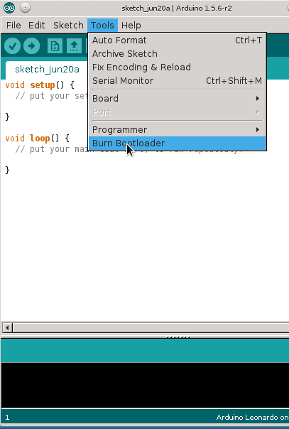
Programmer For selecting a hardware programmer when programming a board or chip and not using the onboard USB-serial connection. Normally you won't need this, but if you're burning a bootloader to a new microcontroller, you will use this.
Burn Bootloader The items in this menu allow you to burn a bootloader onto the microcontroller on an Arduino board. This is not required for normal use of an Arduino board but is useful if you purchase a new ATmega microcontroller (which normally come without a bootloader). Ensure that you've selected the correct board from the Boards menu before burning the bootloader on the target board. This command also set the right fuses.
The IDE environment is mainly distributed into three sections
- Menu Bar
- Text Editor
- Output Pane
As you download and open the IDE software, it will appear like an image below:
The bar appearing on the top is called Menu Bar that comes with five different options as follow
- File - You can open a new window for writing the code or open an existing one. The following table shows the number of further subdivisions the file option is categorized into.
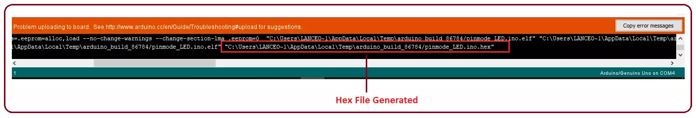
- As you go to the preference section and check the compilation section, the Output Pane will show the code compilation as you click the upload button.

- And at the end of the compilation, it will show you the hex file it has generated for the recent sketch that will send to the Arduino Board for the specific task you aim to achieve.
- Edit - Used for copying and pasting the code with further modification for font
- Sketch - For compiling and programming
- Tools - Mainly used for testing projects. The Programmer section in this panel is used for burning a bootloader to the new microcontroller.
- Help - In case you are feeling skeptical about software, complete help is available from getting started to troubleshooting.
The Six Buttons appearing under the Menu tab are connected with the running program as follows.
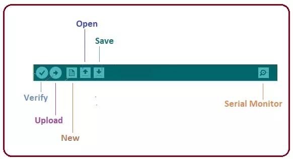
- The checkmark appearing in the circular button is used to verify the code. Click this once you have written your code.
- The arrow key will upload and transfer the required code to the Arduino board.
- The dotted paper is used for creating a new file.
- The upward arrow is reserved for opening an existing Arduino project.
- The downward arrow is used to save the current running code.
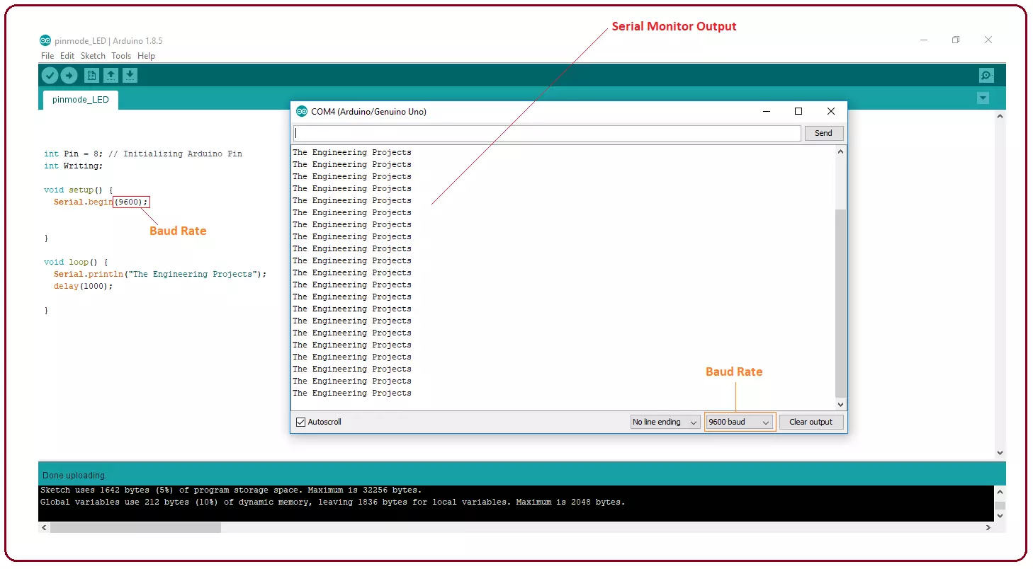
- The button appearing on the top right corner is a Serial Monitor - A separate pop-up window that acts as an independent terminal and plays a vital role in sending and receiving the Serial Data. You can also go to the Tools panel and select Serial Monitor, or pressing Ctrl+Shift+M all at once will open it instantly. The Serial Monitor will actually help to debug the written Sketches where you can get a hold of how your program is operating. Your Arduino Module should be connected to your computer by USB cable in order to activate the Serial Monitor.
- You need to select the baud rate of the Arduino Board you are using right now. For my Arduino Uno Baud Rate is 9600, as you write the following code and click the Serial Monitor, the output will show as the image below.
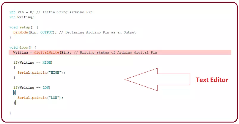
- The main screen below the Menu bard is known as a simple text editor used for writing the required code.
- The bottom of the main screen is described as an Output Pane that mainly highlights the compilation status of the running code: the memory used by the code, and errors that occurred in the program. You need to fix those errors before you intend to upload the hex file into your Arduino Module.

- More or less, Arduino C language works similar to the regular C language used for any embedded system microcontroller, however, there are some dedicated libraries used for calling and executing specific functions on the board.
Getting Started with the Arduino ISP
The first steps to setting up the Arduino ISP
This is a retired product.
The Arduino ISP is an In-System-Programmer that is used to program AVR microcontrollers. You can use the Arduino ISP to upload sketches directly on the AVR-based Arduino boards without the need of the bootloader. Otherwise you can use it to restore the bootloader.
How to connect the Arduino ISP
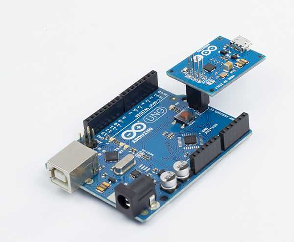
Plug the Arduino ISP on the 6-pin ICSP connector of the Arduino board you want to program, as shown in the picture.
Connect the Arduino ISP to your computer with a micro USB cable, and connect the target board to a power source (USB cable or with the power jack). The target board can also be powered from the Arduino ISP. To enable this feature you have to close the SJVCC jumper, with a soldering iron and a drop of soldering tin.
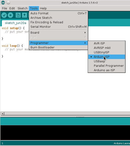
After you made all the connection you have to select the right programmer into the Arduino IDE like shown in the picture.
Burning the bootloader
The bootloader is a small piece of software that allows your Arduino board to communicate with the Arduino IDE when you want to upload a sketch. Normally when you want to load a program on a microcontroller you need an external programmer, like the Arduino ISP. The bootloader eliminates the needs of an external programmer because, the protocol that allows your computer to program the flash memory of the AVR is contained inside the bootloader. All the AVR-based Arduino boards comes with the bootloader pre-installed but sometimes the upload process or some sketches can corrupt the memory where the bootloader resides causing the failure of future upload procedures. Burning again the bootloader with the Arduino ISP can restore the bootloader and bring back your Arduino to upload using the USB port again. You can also use the Arduino ISP to burn the bootloader in a brand new ATmega. If you replace the ATmega microcontroller on your Arduino you will need to burn the bootloader in order to load sketches in the usual way. You can simply do it with the Arduino ISP.
Burning the bootloader is an easy-to-go feature provided by the Arduino IDE. To upload the bootloader on your board just connect everything as described before and click on Burn bootloader in the Tools menu.
Uploading a sketch
The Arduino ISP programmer can be also used to load sketches on the AVR-based Arduino boards or on other AVR microcontrollers supported by the Arduino software.
Uploading a sketch using the standard procedure needs the presence of the bootloader. Instead, by choosing the external programmer as option to upload a sketch will upload the sketch using the entire flash memory space. This may be useful if need more space for the sketch using the memory used by the bootloader.
NOTE: Remember that if you overwrite the bootloader you won't be able to upload other sketches by clicking on the upload button in the Arduino IDE. If you want to use again your Arduino as before, you have to burn the bootloader first.
After you finished your sketch and everything is correctly setup, go on the File menu and click on Upload using Programmer. Alternatively, there is a keyboard shortcut. To upload using the programmer press the keys "CTRL+SHIFT+U".
Programming fuse bits on ATmega microcontrollers.
The Arduino ISP can be used to program fuse bits on ATmega microcontrollers. Programming fuses allows you to configure the internal peripherals and the behavior of the microcontroller. For example you can choose the clock frequency, programming the watchdog timer and much more. This requires some experience and attention because setting these fuses in a wrong way may cause the microcontroller not working anymore, and recovering it may be very difficult.
Comments
Post a Comment