Capacitor
A capacitor essentially consists of two conducting surfaces separated
by a layer of an insulating medium called dielectric. The conducting surfaces
may be in the form of either circular (or rectangular) plates or be of
spherical or cylindrical shape. The purpose of a capacitor is to store electrical
energy by electrostatic stress in the dielectric.
Capacitance,
The property of a capacitor to ‘store electricity’ may be called
its capacitance.
As we may measure the capacity of a tank, not by the total
mass or volume of water it can hold, but by the mass in kg of
water required to raise its level by one metre, similarly, the
capacitance of a capacitor is defined as “the amount of charge
required to create a unit p.d. between its plates.”
Suppose we give Q coulomb of charge to one of the two plate
of capacitor and if a p.d. of V volts is established between the two,
then its capacitance is
C (Capcitance) = Q (Charge) / V (Potential difference)
Hence, capacitance is the charge required per unit potential difference.
By definition, the unit of capacitance is coulomb/volt which is also called farad (in honour of
Michael Faraday)
∴ 1 farad = 1 coulomb/volt
One farad is defined as the capacitance of a capacitor which requires a charge of one coulomb
to establish a p.d. of one volt between its plates.
One farad is actually too large for practical purposes. Hence, much smaller units like microfarad
(μF), nanofarad (nF) and micro-microfarad (μμF) or picofarad (pF) are generally employed.
1 μF = 10−9 F; 1 nF = 10−9 F ; 1 μμF or pF = 10−12F
Incidentally, capacitance is that property of a capacitor which delays and change of voltage
across it.
When capacitors are connected in series, the total capacitance is less than any one of the series capacitors’ individual capacitances. If two or more capacitors are connected in series, the overall effect is that of a single (equivalent) capacitor having the sum total of the plate spacings of the individual capacitors. As we’ve just seen, an increase in plate spacing, with all other factors unchanged, results in decreased capacitance.
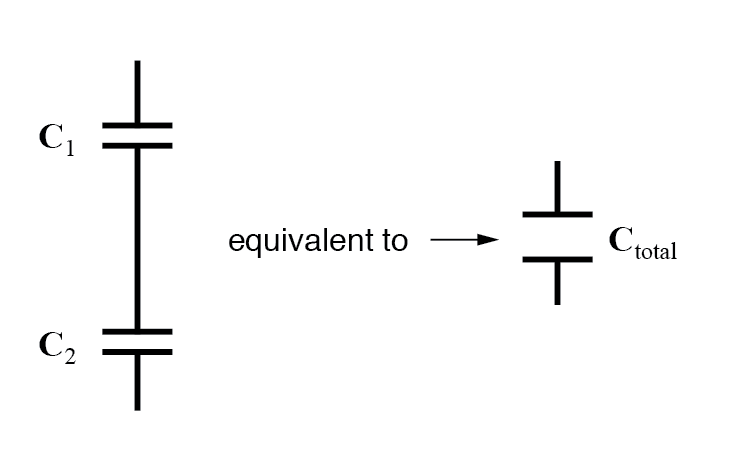
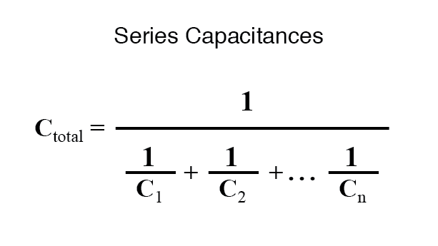
Thus, the total capacitance is less than any one of the individual capacitors’ capacitances. The formula for calculating the series total capacitance is the same form as for calculating parallel resistances:

When capacitors are connected in parallel, the total capacitance is the sum of the individual capacitors’ capacitances. If two or more capacitors are connected in parallel, the overall effect is that of a single equivalent capacitor having the sum total of the plate areas of the individual capacitors. As we’ve just seen, an increase in plate area, with all other factors unchanged, results in increased capacitance.
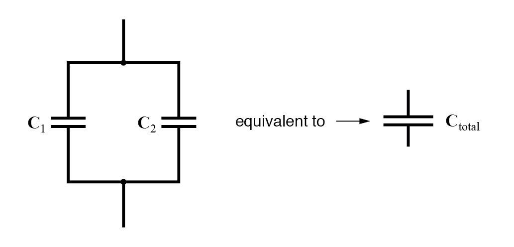
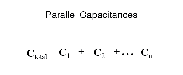
Thus, the total capacitance is more than any one of the individual capacitors’ capacitances. The formula for calculating the parallel total capacitance is the same form as for calculating series resistances:
As you will no doubt notice, this is exactly the opposite of the phenomenon exhibited by resistors. With resistors, series connections result in additive values while parallel connections result in diminished values. With capacitors, its the reverse: parallel connections result in additive values while series connections result in diminished values.


- Capacitors charge gradually until the charging voltage matches the supply voltage.
- When a capacitor is fully charged, it blocks DC current and acts like an open circuit.
- Capacitors can store electrical energy and release it when needed.
- Capacitors can stabilize voltage in DC circuits by opposing changes in voltage over time.
- The time constant, which is determined by the capacitance and resistance in the circuit, governs the charging and discharging behavior of a capacitor.

The charging and discharging rate of a series RC networks are characterized by its RC time constant, , which is calculated by the equation:
Where:
- is the time constant in s
- R is the resistance in Ω
- C is the capacitance in F

The value of most electrical capacitors is expressed in farads, microfarads (µF), or nanofarads (nF).
- The voltage rating of a capacitor can range from 1.5 V to 10,000 V or more.
- Polarized capacitors generally have a lower voltage rating than non-polarized capacitors.
- Different types of capacitors have different voltage ratings:
- Electrolytic capacitors: Typical voltage ratings are 10 V to 35 V at 85°C.
- Film capacitors: DC and AC rated voltage is usually in the range of tens to hundreds of volts. High-voltage types for electric power systems can have AC voltage ratings of several thousand volts or more.
- Electrolytic capacitors: Typical voltage ratings are 10 V to 35 V at 85°C.
- Each capacitor has a maximum voltage that it can handle. If the voltage exceeds the maximum, the capacitor can explode.
- A capacitor's maximum voltage rating is determined by the dielectric fluid that fills the capacitor. If the voltage exceeds the rating, the fluid will not be able to insulate properly.
There are three basic factors of capacitor construction determining the amount of capacitance created. These factors all dictate capacitance by affecting how much electric field flux (relative difference of electrons between plates) will develop for a given amount of electric field force (voltage between the two plates):
PLATE AREA: All other factors being equal, greater plate area gives greater capacitance; less plate area gives less capacitance.
Explanation: Larger plate area results in more field flux (charge collected on the plates) for a given field force (voltage across the plates).

PLATE SPACING: All other factors being equal, further plate spacing gives less capacitance; closer plate spacing gives greater capacitance.
Explanation: Closer spacing results in a greater field force (voltage across the capacitor divided by the distance between the plates), which results in a greater field flux (charge collected on the plates) for any given voltage applied across the plates.

DIELECTRIC MATERIAL: All other factors being equal, greater permittivity of the dielectric gives greater capacitance; less permittivity of the dielectric gives less capacitance.
Explanation: Although it's complicated to explain, some materials offer less opposition to field flux for a given amount of field force. Materials with a greater permittivity allow for more field flux (offer less opposition), and thus a greater collected charge, for any given amount of field force (applied voltage).
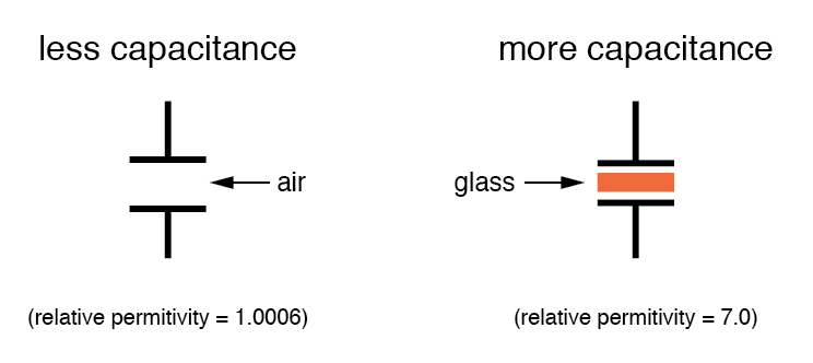
“Relative” permittivity means the permittivity of a material, relative to that of a pure vacuum. The greater the number, the greater the permittivity of the material. Glass, for instance, with a relative permittivity of 7, has seven times the permittivity of a pure vacuum, and consequently will allow for the establishment of an electric field flux seven times stronger than that of a vacuum, all other factors being equal. The following is a table listing the relative permittivities (also known as the “dielectric constant”) of various common substances:
Material
Relative permittivity (dielectric constant) Vacuum 1.0000 Air 1.0006 PTFE, FEP (“Teflon”) 2.0 Polypropylene 2.20 to 2.28 ABS resin 2.4 to 3.2 Polystyrene 2.45 to 4.0 Waxed paper 2.5 Transformer oil 2.5 to 4 Hard Rubber 2.5 to 4.80 Wood (Oak) 3.3 Silicones 3.4 to 4.3 Bakelite 3.5 to 6.0 Quartz, fused 3.8 Wood (Maple) 4.4 Glass 4.9 to 7.5 Castor oil 5.0 Wood (Birch) 5.2 Mica, muscovite 5.0 to 8.7 Glass-bonded mica 6.3 to 9.3 Porcelain, Steatite 6.5 Alumina 8.0 to 10.0 Distilled water 80.0 Barium-strontium-titanite 7500 An approximation of capacitance for any pair of separated conductors can be found with this formula:

Comments
Post a Comment